CHRIS AND FRAN BARLEY'S FUSELAGE NOTES
(First published in AJ's Airborne reproduced with
kind permission)
The majority of these notes were originally supplied to Jim Wills
(probably circa 1996), following his request in the Squadron Newsletter
for comments on the plans. We then subsequently supplied them to Tony
Anderson. Unfortunately circumstances have meant that they haven't
been widely seen, although some earlier hand written notes of ours
have been circulating around some builders. We have always been very
keen to pass on our experiences to other builders to help them, just
as we were given fantastic help in the early days.
1. Drawing No 9 - Firewall Strut The front strut immediately behind
the firewall contains some detail 11 3/4" down from the top longeron.
The purpose of this detail is unclear. (I have discussed it with Jim
Wills by phone and Jim advised it should be ignored, as it was associated
with engine types other than the Continental series - ie Ford A or
Corvair).
2. Drawing No 9 - Large Gussets Large gussets (21 1/2" x 5 3/4")
are shown at the front, upper inboard faces of the fuselage sides.
These seem to be particularly related to the Ford 'A' version "tray"
and it is not clear whether they should be included on the Continental/other
powered versions. Jim Wills advised by phone that they are not strictly
required for Continental versions, but we decided to include them
anyway, as do most other builders. They will help reinforce this area
for fuel tank mounting if you decide to use a fuselage tank.
3. Drawing No 1 - Rear Seat Back The rear seat back is shown on the
drawing as a 21 3/4" wide x 21" deep rectangle. Since it forms a vital
jig when aligning the 2 fuselage halves we accurately pre-made ours
to the dimensions shown and then used it to jig up and locate the
sides. Unfortunately because the seat back is inclined within the
fuselage the bottom edge needs to be slightly wider than the top edge,
i.e. the bottom edge sits in a wider part of the fuselage than the
top edge. If the seat back is pre-made as a proper rectangle it will
not fit properly. (NB the references to bottom and top edges are true
edges. Since the fuselage is assembled upside down on the building
table, the true bottom edge of the seat back is actually uppermost!).
4. Drawings 1 & 3 & 47-003 - Ash Cross Member Drawings 1 & 47-003
call up ash cross members which are 2" x 3/4" in cross section. Drawing
3 calls up for a forward beam which is 2" x 1" in cross section with
its ends tapered to 2" x 3/4". We followed the drawing 1 & 47-003
requirement.
5. Drawings 1 & 9 - Tailplane Mounting Drawing 1 gives a dimension
of 18" between the end of the turtledeck and the end of the tailpost.
Drawing 9 quotes 18 7/8". Since the tailplane chord is 18" we have
made ours approx. 18 1/8" to allow a small clearance between the tailplane
leading edge and the rear face of the turtledeck.
6. Drawing 1 - Fuselage Width Drawing 1 quotes 24" for the fuselage
width, with the note that "all dimensions to outside of ply". However
47-004 sheets 1&2 imply that the fuselage is actually 24 1/4" wide
across the skins. Ours has been made 24 1/4" wide, but we know of
others which are 24". It probably doesn't matter much since the pick
up points on the engine mounting are very flexible and can easily
accommodate a ¼" difference. However, there is also a need to consider
where the centres of the centre-section cabane strut brackets sit
in relation to the fuselage longerons. With the centre-section brackets
positioned as per drawing and the cabane strut centralised within
it, a fuselage width of 241/4" allows a comfortable fit at the bottom
end of the strut with the strut slightly favouring the outside of
the pair of fuselage brackets. Plenty of space is then available for
the outboard fillet of braze between bolt bush and cabane strut. With
a fuselage width of 24" you may need to offset the cabane strut slightly
in the centre-section brackets to get enough space for a good sized
fillet at the bottom end. Not a problem, but something it's nice to
be aware of.
7. Drawing 1 & 9 - Tail Thickness After Assembly No dimension is
quoted for the thickness of the tail-post after joining the two fuselage
sides together. Since the main beams of the tail components are all
1" thick at this point, logically it should be the same, but it is
not dimensioned. We made ours 1" thick. If you vary the tail surface
main beams (as some builders have done - we haven't), bear this in
mind.
8. Drawing 1, 4 & 9 - Bellcrank Position Various dimensions are
quoted for the position of the bellcrank above the bottom longeron
lower surface ply. Drawing 4 quotes 9", drawing 9 quotes 7 1/8" and
drawing 1 quotes 7". We are using the largest dimension to try and
avoid the control cable to the upper elevator horn rubbing on the
tailplane leading edge, as many do. Pietenpol G-BKVO cunningly uses
an eye and rod arrangement to prevent this though, as on Tiger Moths.
9. Drawing 1, 4 & 9 - Bellcrank Mounting Consideration needs to be
given to sanding the vertical strut surfaces flat where the bellcrank
mounts. Since this would weaken the strut, we glued 3" x 1" x 1/4"
ply plates at the mounting faces, before sanding. These ended up with
a 1/8" x 1/4" wedge shape after sanding. We used a 3 foot piece of
6" wide Contiboard shelving with abrasive paper stuck to one face
and a 2"x2" batten stuck to the other forming a stiffener and handle,
as a sanding block.
10. Drawing 1 & 9 - Seat Back Mounting As per item 9 above, the vertical
strut faces where the rear seat back mounts need to be sanded flat
with one another before trying to glue in the seatback. We set our
fuselage sides to the correct plan-form before offering up the seat
back (see item 11). The need for some sanding was immediately obvious.
We used the same sanding block as in item 9.
11. Drawing 1 & 47-003 - Floor Ply Thickness Drawing 1 quotes a floor
ply thickness of 7/32". 47-003 contains a sectional note giving the
floor ply thickness as 1/4".
12. Seat Belt Attachments This is the most worrying of all the areas
of uncertainty within the drawings. I discussed this issue in about
1994 with Francis Donaldson and he advised me to follow the advice
contained in a back edition of Popular Flying ( Jan 1990 edition,
page 28). This ultimately says that all systems must be approved by
PFA Engineering. We've basically used this information and copied
some of the arrangements used in G-BUCO. The only area that isn't
yet sorted out is the difficult one ie the front seat upper restraint
attachment point. An earlier edition of Aircamper 'Appenings and the
letter from PFA containing Hal Danby's system will be a great help
when it comes to finalise the arrangements. Unfortunately our fuselage
was completely finished early in 1996 and we've recently discovered
that our aileron cables coincide more or less with the position where
the bottom cross tube of the Hal Danby designed harness frame will
go. Hal didn't have this problem (discussed at Sywell 2000), but we're
going to have to work out a way around it on our aeroplane.
13. Fuselage Side Planform To hold the fuselage sides in their correct
plan positions we used blocks fixed to the building table to locate
the true top longeron (fuselage being assembled upside down) and lengths
of threaded rod to locate the true bottom longerons. At each point
we used two lengths of threaded rod passing through wooden blocks
to sandwich the longerons. A bonus was that it allowed the longerons
to be eased apart to provide clearance for gluing and then closed
up again a controlled amount. This avoided all the glue being wiped
off and retained the accurate dimension. See photo and sketch for
detail. Bottom Block Longerons Rod Nut Strut Top Longerons Block Table
14. General - Cutting Of Diagonal Braces The fuselage drawings 1
& 9 tend to indicate that diagonal braces may be cut to a point, whereas
other references we have seen insist that they be cut to a double
tip. Hopefully the sketches clarify, we've assumed both are acceptable
though since it's the ply gusset provides the load path. Most of ours
are double tipped though.
15. Centre Cabane Strut Fitting Dimensions Drawing 5 shows the aerofoil
section and shows that the spars are on 28 3/4" centres (27 11/16"
+ (1 1/8)/2 + 1/2"). Referring to drawing 9, if the rearmost cabane
strut fitting is positioned over the 3" x 3/4" doubler clearly labelled
as being for this purpose, the centreline of spruce fuselage strut
no 3 is actually going to be 28 3/4 " + 5/8" away. Therefore the two
cabane struts will be closer together at the top than at the bottom.
Whilst this probably doesn't matter, it does seem odd. A further concern
at this same point is that the brackets securing the main cabane struts
to the fuselage do not line up with the struts themselves. Therefore
there will tend to be a turning moment on the brackets which appears
undesirable, but most flying Pietenpols seem to have this feature
and manage quite happily.
16. Drawings 1 & 9 - Rearmost Side Gusset No horizontal dimensions
are given for the rear gusset which glues to the top longeron, bottom
longeron and tailpost. We made ours 4.5 inches wide at the top and
7.5 inches wide at the bottom. This applies on the port side fuselage
frame only. On the starboard side the whole of the last bay has a
narrow plywood frame with a rebated lip to allow an inspection panel
to be fitted.
17. Tailwheel Spring Mounting It is beneficial to incorporate an
ash wedge into the apex formed by the lower longerons at the rear
of the fuselage if a conventional leaf spring mounted tailwheel is
to be used (as opposed to the drawn A-frame and coil spring type).
We also added 1/8 inch ply on the bottom of the whole rear bay and
on the top surface of the ash wedge. We were conscious of the need
to minimise weight at the tail end and only did the minimum reinforcement
considered necessary.
18. Rear Bay Dimensions The drawing showing the lengthened fuselage
gives no width information This has to be obtained from the original
fuselage drawing instead. We chose to keep the bay widths the same
ie on the lengthened 1966 fuselage, the first vertical strut forward
of the tail post, where the width of 5.5 inches occurs, is 19 inches
from the tailpost rather than 16.5 inches. The knock on of this though
is that the standard tailplane brace wire fitting on the underside
of the fuselage is not the correct dimensions as it now fits on a
narrower fuselage width. Others have simply kept the bay widths at
various stations the same as for the original fuselage. We don't think
it matters either way, but it's worth being aware of this point. On
the underside of the fuselage immediately forward of the rear bay
the original fuselage drawing shows an extra crossmember. We haven't
incorporated it, thinking that it is only associated with the A frame
tailwheel mount. If you are using a leaf spring tailwheel assembly
it is neater to coincide the spring's attachment point with the brace
wire attach bracket. A single bolt can secure both, and if it passes
through the ash wedge mentioned in item 17 a good solid attachment
results, with no weakening of the fuselage caused by having 2 holes
close together. It does mean that the brace fitting is further aft
than drawing, but this is unlikely to be a problem since it tends
towards the upper brace wire arrangement, where the brace wires meet
at the top rear edge of the fin.
19. Fuselage Frame Nodes On our aircraft, all the spruce member nodes
in the cockpit area of the fuselage side frames are filled with spruce
wedges, not just the ones where the undercarriage mounts.
20. Control Column to Bellcrank Cables We have fitted a twin pulley
assembly at the bottom edge of the rear seat, aft face to guide the
cables through the change of angle that exists here. A very small
depression (1/8" deep) was sanded in the seat cross strut at this
point to allow the cables to sit higher up than would otherwise have
been the case. This prevents the cables rubbing against the top of
the control column torque tube rear bearing housing and keeps the
cables in firmer contact with the pulleys mounted at the rear of the
torque tube. Greater cable tension would have achieved the same result
but gave an unpleasant over-centre feel to the elevator control and
felt to be overloading components unecessarily.
21. Coaming Reinforcement When making the coamings from 1/16 inch
ply, it is worthwhile adding a 1/16 doubler to reinforce the lip that
projects rearwards from the plane of the instrument panel. This avoids
any damage occurring through knocks when getting in and out of the
cockpits. I can confirm that you will hurt yourself rather than damage
the aircraft (my elbow is still tender 2 weeks after thumping it into
such a reinforced edge).
22. Cockpit Area Skining If you use an 8ft X 4ft sheet of ply cut
through the middle for the two sides, it would be best to check that
it will be deep enough. It may be necessary to ensure that the skin
stops at the bottom longeron lower surface and lap the floor piece
over it, rather than overlap the other way. This is because the ply
panel may not be quite deep enough otherwise (you will need it to
be 24 inches deep, and a 48 inch wide panel cut in half will be slightly
too shallow). Using scarfed GL1 ply panels cut in half shouldn't be
a problem as they are typically 50 inches wide (just under 25 inches
when cut in half).
23. General Areas Where Lack Of Information Exists · Bear in mind
the need to consider fuselage water drainage requirements. You need
to anticipate where water may gather and provide drain holes. Particularly
tricky areas are the lower tailpost areas and where the turtledeck
meets the top fuselage surface. We've put drain holes in all our lower
fuselage side frame gussets and in front of all cross.members in skinned
bottom fuselage areas. · Access panel requirements are important considerations.
We embodied a rear fuselage side panel below the tailplane (see item
16 above) and panels below the bellcrank assembly, similar to G-BUCO.
· Advice is needed by novice builders on the required grain direction
for ply panels. This appears on the supplement drawings but isn't
on the older drawings. It's not always that obvious and a mixture
is seen on the flying examples. · When fitting in a large fuselage
fuel tank it will be necessary to design in extra structure to take
the new loads. We elected to retain the original model A type tray
and vertical wall (in 1/4" ply) on which to sit our intended tank.
The large front internal gussets were also retained for this purpose
to help spread the loads into the fuselage frames.
c.barley@ntlworld.com
|
 Jan 2001
 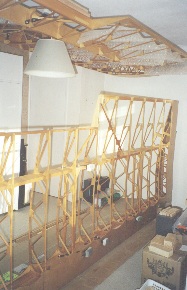 Jan 2001